How To Choose The Correct ZCCCT Turning Insert For Your Application
What are turning inserts?
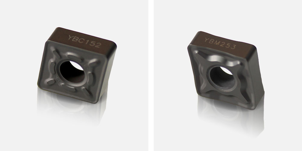
Turning inserts are used on a CNC or manual lathe to remove material from the workpiece. The turning inserts from ZCC-CT are made of solid carbide and are specifically designed for cutting metal.
Carbide turning inserts are generally manufactured to ISO standards and are available in a range of geometries, chip breakers and grades
The swarf generated from cutting metal on a lathe is broken up into pieces and discarded. The chip breaker refers to the pattern on the insert which helps in this process. ZCC-CT have a large selection of chip breakers to help manage the swarf for a large range of materials and cutting conditions.
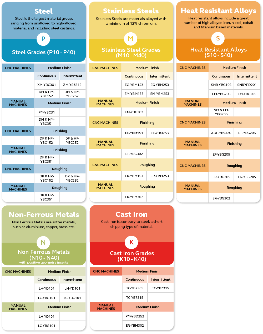
The grade refers to the coating on the turning insert. Different coatings help maximise the cutting performance for different types of metal, for example stainless steel and cast iron etc. ZCC-CT have grades suitable for machining a wide range of materials including steels, stainless steel, cast iron, heat resistant alloys and other non-ferrous metals. Grade are discussed in more detail further below.
The structure of the turning insert SKU is determined as follows:
ISO Standard
Style: CNMG
Size: 1204 - This is broken down further so the cutting edge length is 12mm, the insert thickness is 4mm
Radius: 08 - This means the radius is 0.8mm
Specific to ZCC-CT
Chip breaker: EM
Grade: YBM253
The syntax is [STYLE][SIZE][RADIUS]-[CHIP BREAKER] [GRADE]
The resulting turning insert SKU would be CNMG120408-EM YBM253 (Which is one of our most popular inserts! Recommended for maching stainless steel)
Please click here for greater indepth details regarding the coding structre


What To Consider When Choosing A Turning Insert
There are many things to consider when selecting the correct turning insert such as:
- Are you roughing or finishing?
- What material are you machining?
- What is your machine type? (manual or CNC)
- Cutting conditions (Continuous or intermittent)
- Approach angle?
Inserts for finishing
Finishing is term given when removing material from the work piece and leaving a smooth surface finish (Hence the name!). This is achieved by removing small amounts of material with each pass.
If you need a fine finish on your application, then we strongly recommend a 0.1 – 0.4mm radius on the insert. Combining this with a dedicated finishing chip breaker on a positive geometry insert, ensures excellent surface finish and less insert wear.
Inserts for roughing
Roughing is the term given when removing large amounts of material quickly form the work piece. This is achieved by making deep cuts with each pass. It is given the term roughing as it usually leaves a rough surface finish.
When taking large depths of cut and removing a lot of material, you need a strong and durable insert to stand up against these tough machining conditions. With negative geometry inserts and roughing chip breakers available ranging from 0.8 to 2.4mm radius, we also suggest a larger edge length on the tip. A more robust and stronger insert allows for bigger depths of cut to be achieved which is deal for heavy duty machining.
Choosing the correct grade to suit the material you are machining
Once you have found the correct insert geometry to suit your application and machine type, you need the applicable grade suitable for the material you are cutting.
With so many grades available, it’s difficult to just choose one.
Here are some tips on how to select the best grade.

CNC and Manual Lathe Machines
CNC lathe machines are preprogrammed and can operate without constant oversight from an engineer. CNC machines are much more accurate than manual machines, can run at higher speeds and can perform much more complicated tasks.
Manual lathe machines require an engineer to constantly adjust the settings whilst in operation.
With more and more CNC machines being integrated into workshops, the requirements for different coatings and insert grades have changed.
When turning on a CNC lathe, a CVD (chemical vapor deposition) substrate has proven to be more successful. CVD coated inserts are designed to endure faster cutting conditions with less wear to give longer tool life. Whereas for manual lathes a PVD (physical vapour deposition) insert gives better results when dealing with lower RPM, speeds and feeds.
Approach Angles
To select the correct approach or entering angle for the cutting tool, you will need to consider the application in mind and the finished machined part profile.
We recommend different inserts depending on your approach angle.
The SNMG insert is ideal for facing applications. The 45-degree angle makes the SNMG insert our 1st choice for facing and removing large amounts of material.
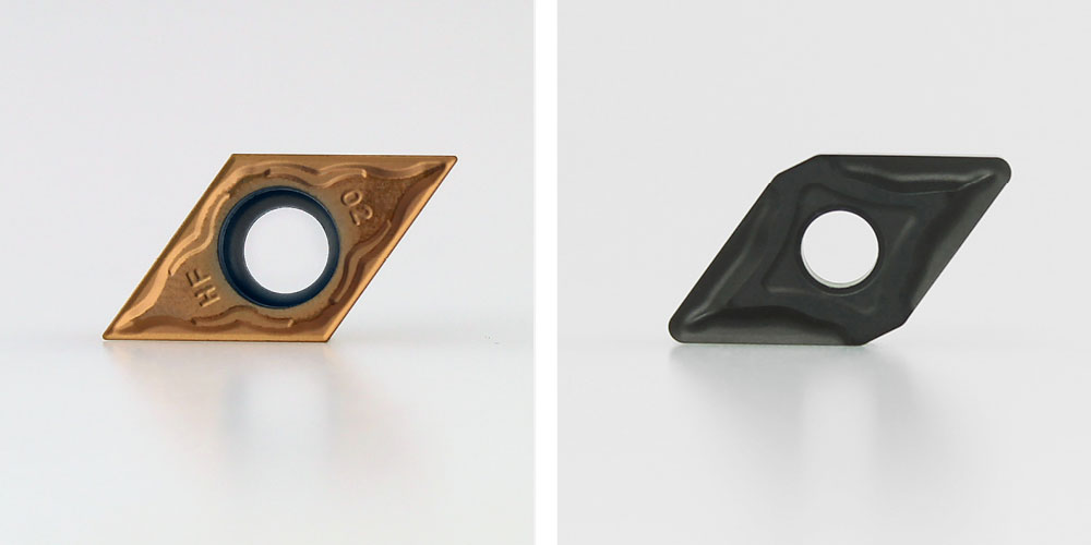
The DNMG and VNMG are ideal for machining profiles.
Depending on machine types, application, angles, the list goes on. There is an insert for every job!
Cutting Conditions
The 2 main cutting conditions are continuous and intermittent cutting.
Continuous cutting is where the turning insert is always engaged with the workpiece. This will enable the work piece to be run at higher speeds.
Intermittent cutting is where the turning insert periodically disengages with the workpiece on each rotation. This requires the insert to be run at lower speeds.
ZCC-CT offer multiple chip breakers to increase performance of the turning insert in each scenario. The chip breaker helps manage the swarf generated from cutting the workpiece.
Choosing the correct turning insert for complicated applications can sometimes be trial and error due to all the different variables.
The turning inserts from ZCC-CT can last much longer and perform at a much higher rate than many of the other big brands available in the UK once the correct turning insert has been found.
Please contact our sales team today and we would be happy to select the correct insert to suit your application.

She is an all-rounder and deals with inbound and outbound queries as well as all our purchasing (because no one else can be a***d doing it!)
